
This is a little weather monitor. It has a 2.2" color display and is powered by an AVR and the ESP8266. The AVR controles the display. The ESP has
a custom firmware written in the Arduino IDE and provides all the weather data in a neat and very simple pre-parsed protocol. The AVR can obtain
different data via a simple UART command. A 512kB serial SPI flash provides all the icons, images and palette data. The system is rounded of by a
DS3231 I²C RTC.
The system features:
- Time and date from DS3231
- Day of week and weeknumber
- Current weather with nice icons and max min forcast
- Current UV data from Internet
- Windspeed and direction
- Humity and preasure
- Sunset and sunrise times
- WiFi strenght indicator, IP and SSID
- Moonphase calculated in realtime on the AVR
- Threeday forecast with icons and max min temperature
- USB connection for power and programming all devices
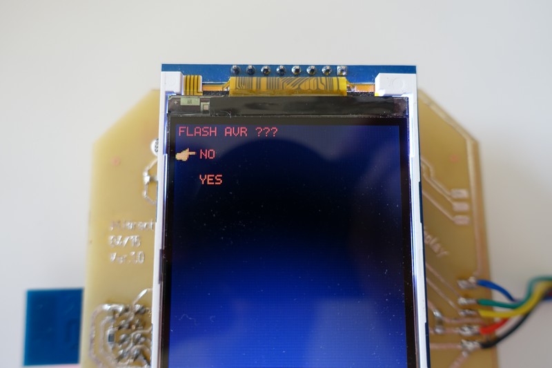
- Simple WiFi config using the ESP as hotspot with a webpage to enter the WiFi credentials. All handeld on the ESP to use in other projects and not bother the AVR. -All the data is obtained and processed on the ESP from public internet sites, no need for external processing like from a Raspberry Pi.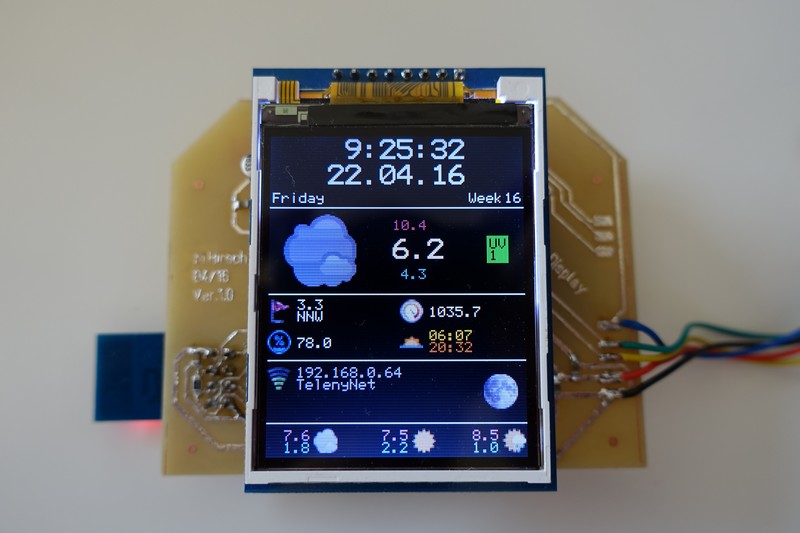 The AVR, external flash and ESP can all be programmed via the USB port. The AVR has a bootloader and two routines to program the external flash and the ESP.
The ESP can be programed directly from the Arduino IDE without any further modification. The AVR handels the datatransfere directly.
For programing the flash and the bootloader I made a few python scripts.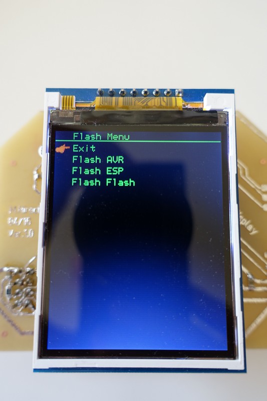 The menu is simple but features a point-finger :-)
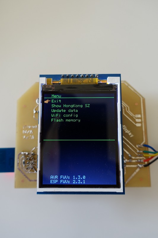 A yes no menusystem.
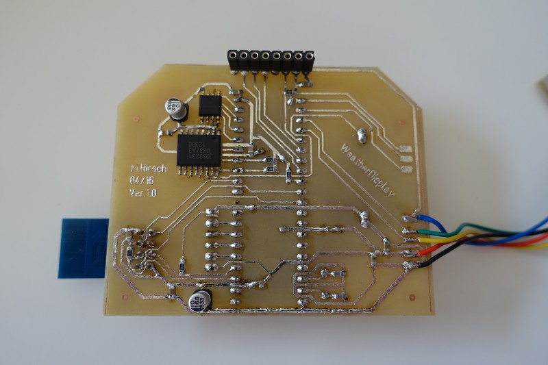
 The self etched PCB. The 512 KB flash and the RTC seen in the left upper courner.
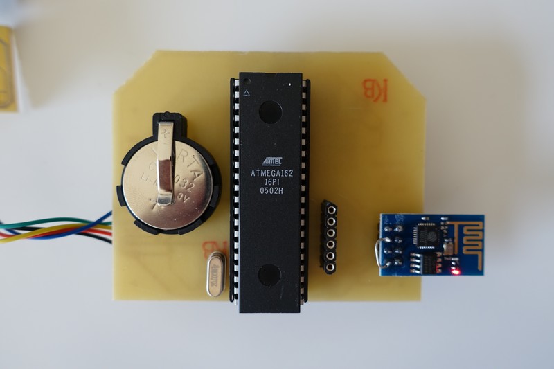
 The circuit fitted on a single sided PCB. Here are the battery for the RTC, the ESP on the right and the AVR with JTAG header for initial programing the bootloader.
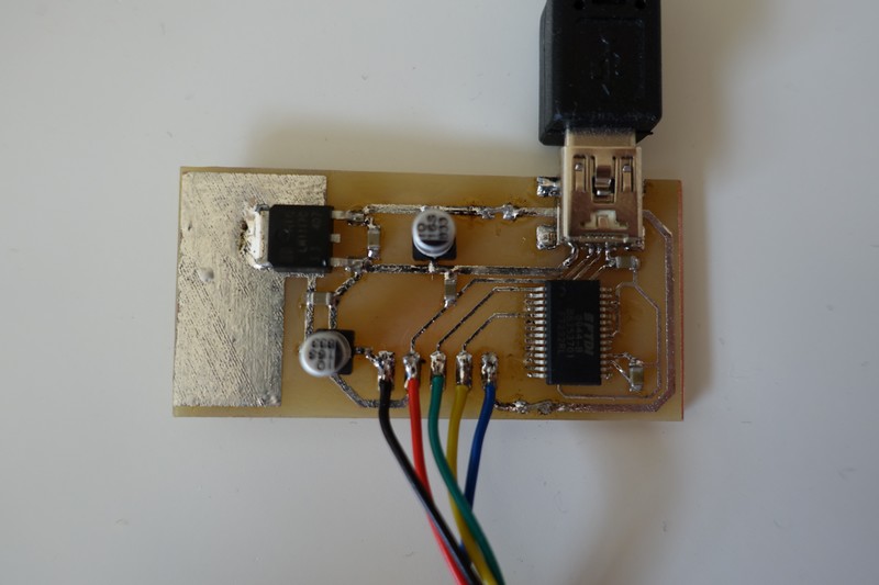
 A standard FT232R provides the USB conectivity.
The project will also get a custom designed case that fitts the functionality. Sofar I only designed it on PC. I hope to soon be able to print it on a 3D printer.
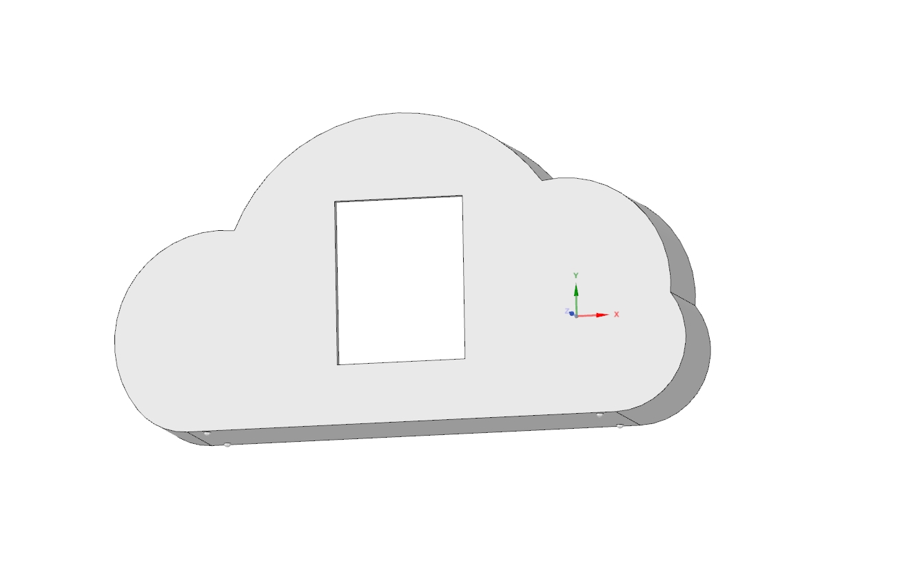 The case will take three PCB's. One main one with the display, the small USB PCB will slide in on the bottom and a third one mounted backwards for the buttons.
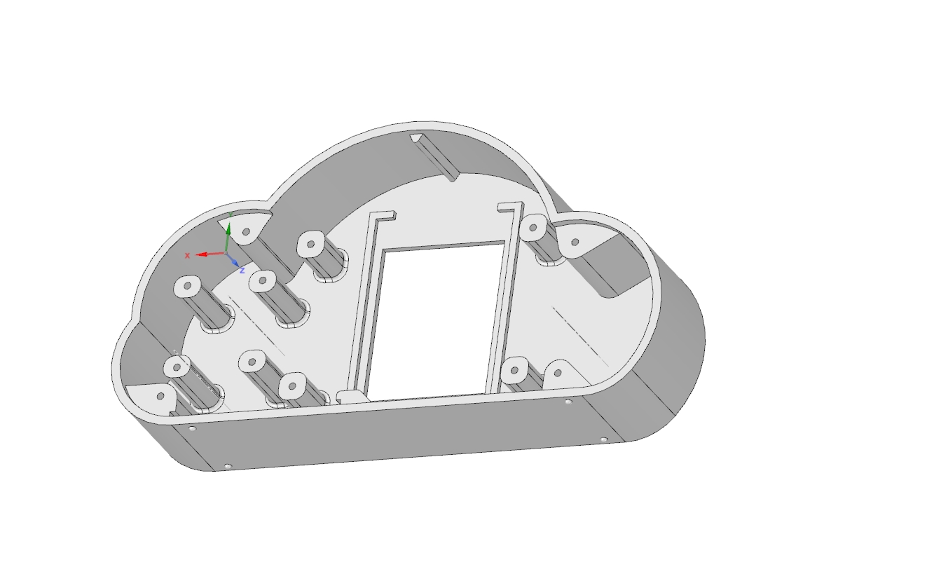 To round the clud of a neat sun will be stuck on on top.
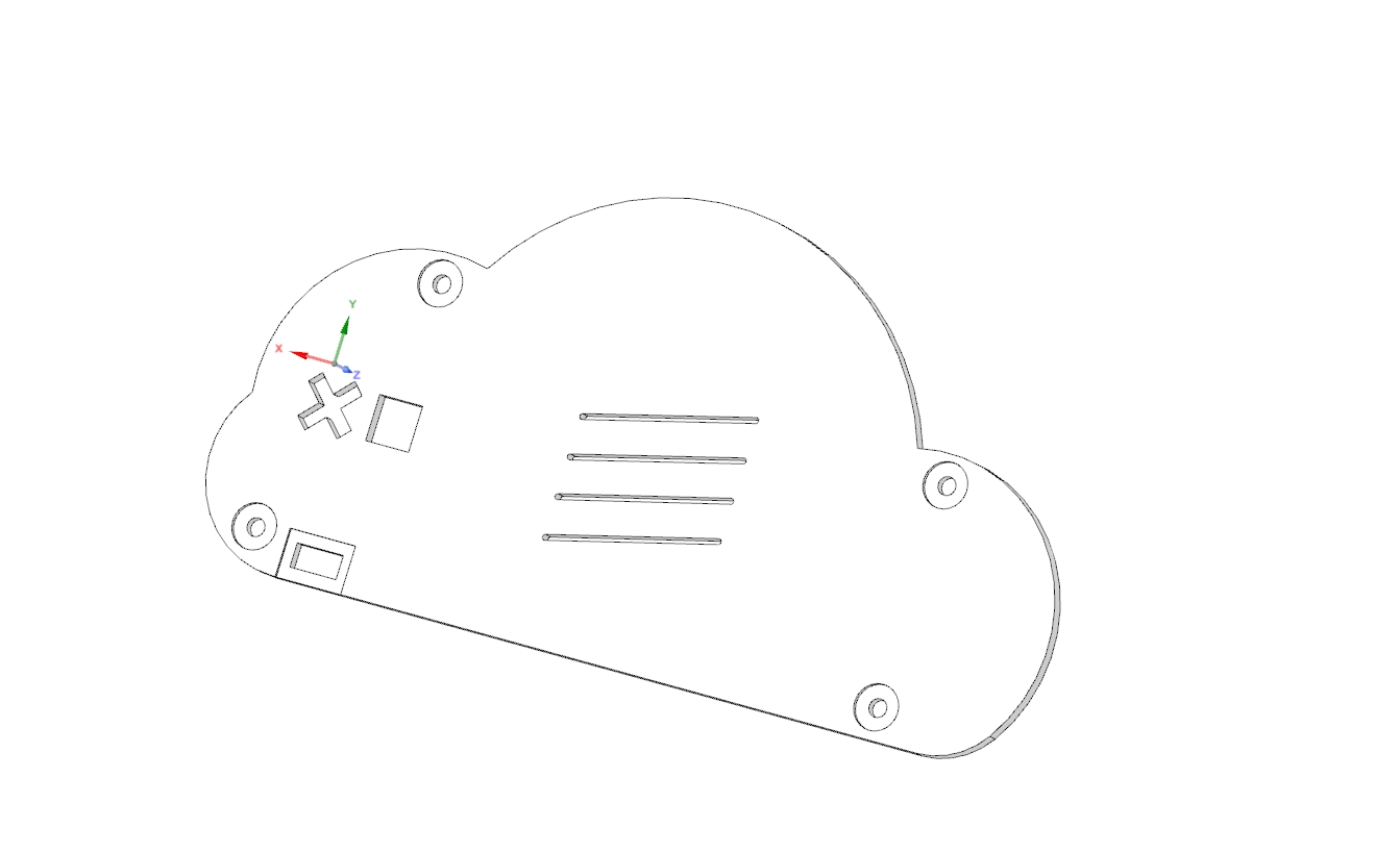
 The lid.
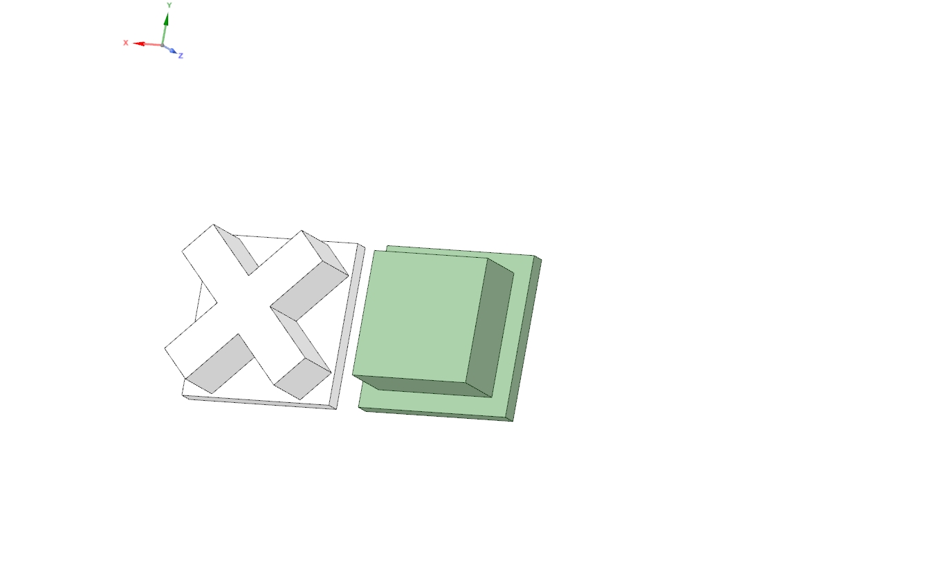
 And the external button covers.
 The scetch was designed with the free DesignSpark 3D.
The system features:
- Time and date from DS3231
- Day of week and weeknumber
- Current weather with nice icons and max min forcast
- Current UV data from Internet
- Windspeed and direction
- Humity and preasure
- Sunset and sunrise times
- WiFi strenght indicator, IP and SSID
- Moonphase calculated in realtime on the AVR
- Threeday forecast with icons and max min temperature
- USB connection for power and programming all devices
- Simple WiFi config using the ESP as hotspot with a webpage to enter the WiFi credentials. All handeld on the ESP to use in other projects and not bother the AVR. -All the data is obtained and processed on the ESP from public internet sites, no need for external processing like from a Raspberry Pi.
The ESP can be programed directly from the Arduino IDE without any further modification. The AVR handels the datatransfere directly.
For programing the flash and the bootloader I made a few python scripts.
The project will also get a custom designed case that fitts the functionality. Sofar I only designed it on PC. I hope to soon be able to print it on a 3D printer.
|
LAST
|
NEXT
|